Module 2 Week 2 During Lab
Goals for This Week
If you need to revisit aspects of last week’s investigation, you should have some time to do so this week by spending less time on the last, open-ended part of this week’s activities.
Your formal, quantitative goal this week is to measure the vertical and horizontal spacing of pixels on the LCD panel we have provided, using a two-dimensional version of the diffraction technique you used in Week 1. Using this information and the physical dimensions of the panel, you will determine the size of the array in pixels from your results. That is, at the end of this week’s careful measurements you will be able to say that the LCD panel is (number \(\pm\) uncertainty) pixels across by (number \(\pm\) uncertainty) pixels high.
All your diffraction measurements up to and including the LCD panel above have been done by transmitting laser light straight through the object being studied. If you wanted to measure your phone screen without tearing it out of the your phone, such an approach would clearly not be viable. Time permitting, you will spend the rest of this week using diffraction gratings, the LCD panel, and/or your phone to explore how diffraction patterns from light reflected off a periodic array relate to diffraction patterns observed in transmission.
Instrumentation
Each station should have an LCD panel in a plastic holder that is fastened to an optical post and mounted on the optical rail. The figure below shows the panel inside a larger acrylic box that you will NOT be using.
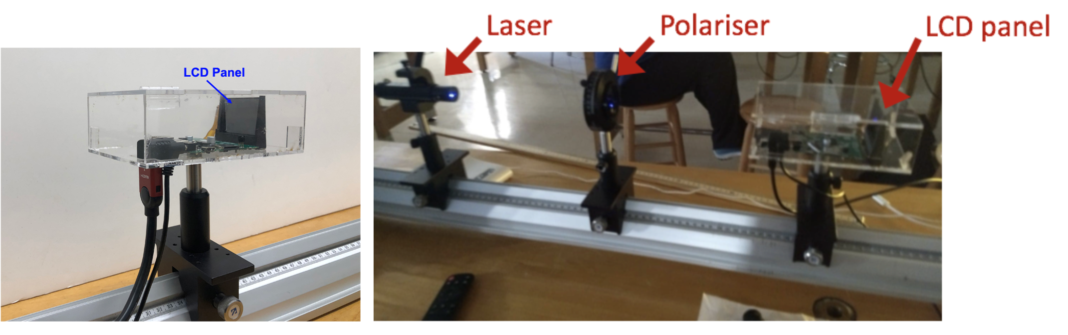
Figure 2 — (left) When you set it up, the laser beam should travel from left to right through the LCD panel. (right) Layout of components on the optical rail. Note that this figure shows the LCD panel inside a larger, clear acrylic box, while your panel in its plastic holder is simply held in a clip mount directly on an optical post. Click on the image to see a larger version.
Figure 3 shows a photo taken of our LCD panel via the eyepiece of a microscope. You may wish to observe an LCD under the microscope (through the eyepiece) in the rear of the lab. A microscope calibration slide is available that you can use to roughly estimate the pixel spacing if you would like.
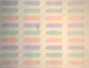
Figure 3 — Microscope image of an LCD panel identical to the one you have on your optical rail. Note: the LCD that is pre-placed in the microscope is the same model as the one on your optical rail. Please do not disassemble your own LCD or its housing, and please do not touch the LCD panel area itself.
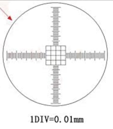 Figure 4 — There is a calibration slide by the microscope that you can use to calibrate length scales in your view. The finest lines in the grid feature near the center of the slide are \(10 \mu m\)
If you are interested in how the LCD panel fits into the overall function of a projector, another LCD panel of the same model can be found at the instructor bench at the front of the lab, along with the complete disassembled projector it came from.
Data Collection
To get a sense of what the diffraction pattern of a two-dimensional grating look like, take two 500-line/mm gratings and stack them like two pieces of paper, but with one grating rotated so its lines are perpendicular to the lines of the first grating. Mount this two-grating sandwich on the optical rail as you would mount a single grating, and shine the laser through both gratings. You do not need to collect any formal data; just describe in your lab notebook what the diffraction pattern from a 2-dimensional grid looks like. Replace one or the other grating with a 1000-line/mm grating and note how the diffraction pattern changes.
Now mount the LCD on your optical rail and shine your laser through the LCD (refer to Fig. 2). You will see a pattern of bright dots creating a rectangular grid, with roughly uniform spacing between maxima. By observing the distance (\(x\) or \(y\)) between these maxima, and finding the values of \(L\) required to produce given \(x\) or \(y\) values, you can determine the spacing of the pixels in both directions. Based on your experience with last week’s investigation, design and execute a procedure for taking reliable data and analyzing it to find the LCD pixel spacing both horizontally and vertically.
The LCD array is \(4.000\) cm wide and \(3.000\) cm tall. You can use the pixel spacing and the physical dimensions of the array to determine the number of pixels horizontally and vertically (with uncertainties).
Finally, use a diffraction grating, the LCD panel, and/or your phone screen to explore what a diffraction pattern looks like when light is reflected rather than transmitted off a periodic array. What about when light shines on the periodic array at an angle and is reflected? Get creative with paper, tape, and mounts to view the reflected patterns as best you can! You could also do some internet research to help make sense of what you are seeing. This portion of the lab might give you some ideas for a tech report at the end of the semester.